


After sale services
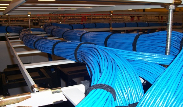
Structured Cabling

Structured cabling is building or campus telecommunications cabling infrastructure that consists of a number of standardized smaller elements (hence structured) called subsystems.
Structured cabling design and installation is governed by a set of standards that specify wiring data centers, offices, and apartment buildings for data or voice communications using various kinds of cable, most commonly category 5e (CAT5e), category 6 (CAT6), and fiber optic cabling and modular connectors. These standards define how to lay the cabling in various topologies in order to meet the needs of the customer, typically using a central patch panel (which is normally 19 inch rack-mounted), from where each modular connection can be used as needed. Each outlet is then patched into a network switch (normally also rack-mounted) for network use or into an IP or PBX (private branch exchange) telephone system patch pane.
Every structured cabling system is unique. This is due to variations in:
- The architectural structure of the building, which houses the cabling installation;
- The cable and connection products;
- The function of the cabling installation;
- The types of equipment the cabling installation will support -- present and future;
- The configuration of an already installed system (upgrades and retrofits);
- Customer requirements; and
- Manufacturer warranties.
The benefits of these standards include:
- Consistency of design and installation;
- Conformance to physical and transmission line requirements;
- A basis for examining a proposed system expansion and other changes; and
- Uniform documentation.
The main components of backbone cabling are:
- Cable pathways: shafts, conduits, raceways, and floor penetrations (such as sleeves or slots) that provide routing space for the cables.
- The actual cables: optical fiber, twisted-pair copper, coaxial copper, or some combination of these. (Note: You should avoid areas where potential sources of EMI or electromagnetic interference may exist when planning the routing and support structure for copper cabling.)
- Connecting hardware: connecting blocks, patch panels, interconnections, cross-connections, or some combination of these components, and
- Miscellaneous support facilities: cable support hardware, firestopping and grounding hardware. Note: The terms horizontal and backbone (previously called riser) evolved from the orientations typical for functional cables of these types. However, the physical orientation of the cabling has no bearing on classifying the cable as horizontal or backbone.
-
آدرس دفتر مرکزی: تهران، بلوار نلسون ماندلا (آفریقا)، خ فرزان شرقی، پ 33
-
تلفن ویژه: 43672 (9821+) 88193969 (9821+)
-
ایمیل: info@mania-co.com